Email ID: info@ksppowercontrols.com
Call Us Today!: (+91) - 98303 68866
An ISO 9001:2015 Certified Company
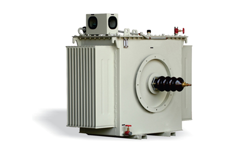
HOME :: High Voltage Rectifier TR
High Voltage Rectifier TR
How about a cleaner Today…and an even Cleaner Tomorrow?
3 Phase High Voltage Rectifiers (HVR) are introduced in India for ESP industry, it was found that the dust emissions were reduced significantly at all installations. Thus by replacing old conventional single phase TR set with 3 Phase HVR TR set, the collection efficiency of existing fields in an ESP seen drastically improved. The objective of this paper is to present the basics of 3 Phase HVR technology, need, Construction, key features, Wave Forms, benefits and comparison with respect to single phase HV rectifiers.Why 3 Phase HVR?
In recent years, due to the increasing awareness towards pollution & changing norms of emissions by the Government Agencies Worldwide, it has become absolutely necessary to achieves higher & higher efficiency so as to reduce the emission from the ESP. The emission requirement from ESP’s is getting lower and lower. In the last decade the emission norm for the ESPs were in the range of 150mg/Nm3 in general. However, due to strict norms by Pollution control boards, the emission levels expected have been come down to almost 50mg/Nm3.There are various ways to do this such as increasing the number of fields, changing the fuels, changing control systems of ESP. However all these things have some limitations in achieving the required result. To achieve higher efficiency beyond certain limits, one should need to increase corona power in the ESP to achieve better & better collection.
Traditionally Single Phase TR sets are used that give high peak voltages for better charging of the particles but the corona current is less and if current is increased to increase corona, it results into heavy sparing / arcing in the ESP. Worldwide there is a change in concept of replacing single Phase TR sets in ESP by 3 Phase TR Sets & it has been observed that there is a substantial increase in the collection efficiency by ESP. Similarly, the emissions can be brought down substantially without any mechanical or process change in existing ESP.
Benefits:
- 1. 3 Phase main Input Supply. Balanced Load on mains power supply. Single Phase TRs create imbalance on the main power supply.
- 2. Lower input line current compared to single phase system. Sizing of input cables and switchgear reduces. This results in cost saving.
- 3. Fast recovery after sparing. Higher average power across ESP field. Higher dust collection and low Emission.
- 4. Low voltage ripple, higher average DC voltage. Heating of cables and switchgear reduces, life expectancy increases.
- 5. Fast response to Sparks and Arcs. Electrode life and durability increases.
Each of the above factors offers potential cost savings for both new and retrofit installations. Lower power consumption due to the improved power factor will result in direct cost savings. There are other potential savings with the cabling and sizing of Switchgears used at the primary size as well as increase in electrode life due to improved spark control action. The product is useful for retrofitting as well as new ESP designs. It is yet to explore but ESP design experts can optimize in new ESP designs to reduce cost either by reducing collection area or reducing ½ fields, in large power plants. All ratings are available and supplied with the highest reliability product and service. Being a rugged transformer and rectifier design the life expectancy is almost 20+ years of operation.
Conclusion:
The introduction of 3 Phase HVR for use on electrostatic precipitators have a number of impacts on the industry. To summarize the major points:- * Improve collection performance.
- * Improved power factor and input harmonic distortion.
- * No need of upgrading ESP fields.
- * Changes to power supply purchasing strategies.
Comparison:
Single Phase TR set Vs 3 Phase TR set (Same Rating)| Parameter | Single Phase TR | 3 Phase TR |
|---|---|---|
| Parameter | Single Phase TR | 3 Phase TR |
| Primary Voltage(v) | 415 V, 3 Phase, 50HZ, (2 Phase) | 415 V, 3 Phase, 50HZ, (3 Phase) |
| Topology | Single Phase Transformer | Delta Star Transformer |
| KV(P) | 110 KVp | 110 KVp |
| Current Rating | 600mA | 600mA |
| KV(avg) Rating | 70 KV avg | 105 KV avg |
| Primary Current (A) | 146A | 96A |
| KVA | 61 KVA | 69 KVA |
| Sparc Quenching Time | 10mS | 3.33mS |
| Ripple Content (%) | 47.20% | 4.00% |
| Operating Frequency (Hz) | 100 Hz | 300 Hz |
| Size of TRCC | 700(W) X 650(D) X 2000 (H) | 700(W) X 650(D) X 2000 (H) |
Performance Improvement Solutions
| PARTICULARS | CONVENTIONAL SOLUTION (ADDITION OF FIELDS) | RETROFIT WITH 3 PHASE POWER SUPPLY |
| Cost Saving | Huge Investment Cost | 70% as compared to Conventional Solution |
| Down Time | More than 6 months | Only 1 day per field |
| Space | Additional Space Needed | Fit in existing space |
| Energy Saving | Poor Power Factor results into more power Consumption | Improved Power Factor Saves 18% power against Conventional Solution. |
